A real control system - how to start designing
Now Playing
A real control system - how to start designing
Transcript
749 segments
hey everyone welcome back to you control
system lectures let's design a control
system the way you might approach it in
a real situation rather than an academic
one now before we begin in earnest let
me take a few minutes to set a little
context for this video you know like I
tend to do I found out quickly when I
graduated college and entered the
working world that it was hard for me to
apply the theory I learned to a
practical application sure if I was
given a mathematical model of a system
and was asked to design a specific
controller I could do that but I lacked
the ability to start a problem from
scratch especially when that problem
seemed nebulous and that there was more
than one right answer where do I begin
how should I model the system and which
type of controller should I choose my
problem came from lack of experience for
sure but the other part came from my
belief that every problem had one best
solution and then they needed to know
before I even started what the proper
approach was going to be I had assumed
that the theory I knew was somehow
outdated and I had learned on the job
exactly how people really do design and
this kept me from just applying the
techniques that I did know to learn from
it even if it's not the optimal solution
but here's the thing there is never a
single right way to solve a control
system problem there are many different
types of controllers that will produce
satisfactory results and there are
numerous ways to model test and
implement that controller if you ask for
engineers you'll probably get five
opinions on how to go about designing
something part of this is because in
addition to meeting your performance and
stability requirements there are a lot
of other aspects of engineering design
that are just as important cost schedule
mass power and manufacturability just to
name a few and a good solution must
consider them as well often you won't
know what a good answer will look like
until you jump into the problem and
start exploring it take a few wrong
turns and evolve your solution over time
until you're left with something that is
ok and those four engineers with five
opinions might all wind up with
different but perfectly okay solutions
as well so keep that in mind as we walk
through just a single approach in this
video now this is going to be packed
with a lot of information and it's going
to be presented quickly
without a whole lot of explanation you
may not be able to follow along with
everything that I go through but that's
alright it's the process and the
excitement of exploring a new problem
that I want you to take away from this
hopefully this will motivate you to go
off and tinker with some real hardware
and practice the theory that you're
learning so that you develop your own
method for tackling new designs that way
you're a little bit more knowledgeable
and at ease when you're given one of
those open-ended problems at work okay
so with all of that out of the way
let's get to our own open-ended problem
we're part of a team that is developing
an earth orbiting satellite and at the
moment we're mostly concerned with the
vehicles thermal control system that's
the system that keeps everything within
the right temperature range space is
cold and parts of the satellite that are
exposed to deep space can get very cold
like minus 150 degrees C or colder but
the parts that directly face the Sun can
get very hot up to 120 degrees C or more
and as the spacecraft orbits the earth
and goes into and out of eclipse and
rotates around the thermal gradient from
one side of the vehicle to the other can
be very extreme and changing all the
time the interior of the spacecraft is
protected from these extreme temperature
swings a bit because they sit within a
mass that has some thermal inertia if
you look at a typical temperature plot
over time the external temperatures tend
to swing wildly since they're not
protected while the internal
temperatures have that low pass filter
of thermal inertia smoothing out the
swings and creating a less dynamic
environment even still some internal
components can see temperatures that are
outside of their desired operating
ranges and we need to figure out a way
to maintain their proper temperature
let's say for this example that we
predicted the average internal
temperature for our spacecraft to be
around -5 degrees C so what does that
mean for us
well our spacecraft has batteries and
they like to operate between ranges like
0 to 20 degrees Celsius or so it depends
on the battery chemistry so if it gets
outside that range the spacecraft and
the entire mission could be in trouble
and our job is to develop a way to keep
the batteries in this temperature range
and since we predict the average
temperature to be rather cold most
likely we will need to warm them up
rather than cool them down a reasonable
approach could be to use passive thermal
control
like rap being multi-layer insulation or
an M Li blanket around it so that it
traps the heat in just like a regular
blanket or we could use thermal straps
that connect it to another hotter
component to move heat towards it but on
this particular project it was already
decided for us that we would control the
battery temperature with a dedicated
strip heater if you have the power to
spare then a heater is a robust way to
ensure that the lower bound temperature
will not be exceeded you have a lot more
control over it with a heater and a
temperature sensor bonded to the battery
now the heater batteries temperature
sensors and the computer that will run
the heater controller were all chosen by
a different team long before we were
asked to solve this problem so we get to
work with what we're given and now that
we know the nebulous problem that we've
gotten ourselves into I think for the
next step it's important to understand
the physics of your system at least
qualitatively if not mathematically
before you just jump right in on
crafting a control solution I like to
think about how the system can move and
what it does when it's subjected to
forces where does the energy come from
how is it dissipated what are the
sources of errors and disturbances in
the system I'd like to have this general
understanding before I start because it
helps guide me later on when I feel
stuck on a particular problem a thermal
control system is all about heat
transfer if we think of the battery
system as a closed boundary then heat
goes into that boundary and heat can
leave that boundary when it's in steady
state operation the idea is to supply
the exact same amount of heat into the
system that is lost out of it so that
the temperature stays the same or at
least within acceptable bounds from a
simplistic standpoint if more heat
enters the boundary then leaves the net
heat transfer is into the battery system
and the batteries will get hotter and
the opposite is true if more heat leaves
then enters then the battery will get
colder
so what are the heat transfer mechanisms
well we have conduction radiation and
convection are the possible ways for
heat to enter and leave this system
conduction is the flow of heat through
individual particles bumping into each
other and transferring energy between
them when a high energy or high
temperature particle
bumps into a lower energy particle some
of that energy is transferred this type
of heat transfer occurs when there is a
physical interaction like we have
between the strip heater and the battery
and the battery with the spacecraft
structure so we need to pay attention to
these physical connections thermal
radiation is the transfer of heat
through photons or another way of
putting it through electromagnetic
energy in the infrared spectrum it's
like how the predator sees things with
his heat map vision actually on a side
note I think it's amazing actually that
every object warmer than absolute zero
gives off photons
it's a crazy concept to think that
humans are just lightbulbs in the
infrared
all right well our battery system emits
photons also which are absorbed by the
surrounding structure which then emits
it off into deep space or if we're in
the Sun the photons from the Sun radiate
into our spacecraft heating it up
lastly convection is when you physically
move hotter particles out of your system
as opposed to conduction where the
particles stay and just the energy is
transferred we experience convection on
earth when the wind blows and physically
moves the hot air particles that were
surrounding our body away from us taking
their thermal energy along with it
there's not a whole lot of convection in
space at least not for our battery
system and hopefully that's obvious so
we don't have to worry about air or
other bulk masses moving heat around
however as you'll see later we do have
to deal with convection as a source of
error when we're testing our system on
earth now the heat sources for our
system come from the Sun as I've already
mentioned but there's also internal
heating due to the battery's internal
resistance and from other hot components
in the spacecraft radiating and
conducting in and of course from our
heater and our heaters the thing that we
have the control over as for error
sources there are a few but I want to
highlight just one the temp sensors
themselves will have error in the
reading and probably more importantly
they only represent a single temperature
point on the batteries if the
temperature isn't homogeneous we may
have problems with part of the battery
getting too hot or too cold and our sins
are not being in the right spot to
measure it
so where should we go from here well if
we knew the battery system perfectly
that is how much heat enters and leaves
the system while on orbit and we knew
how the Delta heat changed the
temperature of the battery system then
we could just set the heater to the
proper supply value to make up the
difference and be done this is an
open-loop control design because the
heater setpoint doesn't rely on feeding
back the battery temperature with this
design if we're wrong about the outgoing
or incoming thermal energy then the
battery temperature will be off from
what we desire and the controller will
have no way to compensate for that error
it's a predetermined set point now this
might be a good approach if the system
was going to operate in a well
controlled environment however that is
not space because the external
environment is always changing we have
different spacecraft components that are
being turned on and off there's eclipse
as it orbits and different spacecraft
rotations to take into account even the
sun's output changes over time know the
open-loop approach feels risky for a
critical spacecraft component because I
don't have confidence that we can
predict the environment that well so we
should implement feedback control at
least of some type we need something
that determines the heater setpoint
based on the actual temperature of the
battery system something that feeds back
the temperature in order to do that we
need a temperature sensor now the temp
sensor the heater and the battery system
are all hardware components to get to
where we can develop a software based
controller we need some kind of sensor
manager that can read and interpret the
voltage from the sensor and produce a
meaningful measure now with this
measured temperature we can subtract it
from our desired temperature to get an
error term or how far off our actual
temperature is from the desired
temperature for example if we wanted the
battery to be at 10 degrees C but it was
measured to be -5 degrees C then there
would be a plus 15 degree difference and
we would need our heater to supply more
heat this is fed into a controller that
takes that error and tries to calculate
the right heater setpoint when we're
developing a controller we're trying to
determine how that conversion is done
and the output of that controller would
go into a heat manager which would
generate the voltage
needed to drive the heater alright now
that we've connected the battery
temperature back to the heater setpoint
we have the framework for our feedback
control system but now what well
unfortunately we weren't given any
transfer functions for the heater the
battery system or the temperature sensor
and I don't want to create a control log
without knowing a bit more about the
system for example it's important to
know how the system will behave when
subjected to actuator commands or in
this case what does it do when we turn
on the heat if we don't have that it
seems a bit like shooting in the dark
and to proceed we need to know more
about the physical hardware and luckily
we do have access to a physical test bed
with RealFlight components so let's play
around with those and see what we can
learn in this video the hardware I'll be
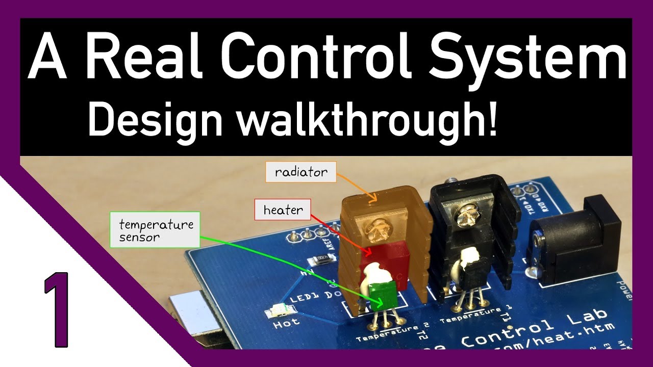
using is this temperature control lab
which runs on an Arduino microcontroller
clearly this is not real spacecraft
flight components but for this video it
will still do just fine because it has
heaters sensors thermal mass and a
computer just like our problem we'll be
able to learn a lot from operating this
hardware but to tie it back to our
spacecraft you'll just need to use a
little imagination let's walk through it
in more detail there are two sets of
heaters and temp sensors but we're just
going to use a single one for our test
the temp sensor is highlighted in green
and it's bonded to the heater in red
with white thermal epoxy in between the
two the thermal epoxy creates a good
conductive path between the heater in
the sensor surrounding the heater is a
radiator that helps distribute the heat
and gives the system a bit of thermal
mass there are no physical batteries in
this test hardware however these
radiators will serve the same purpose
they are a thermal mass that we can heat
up and when hot they lose heat to their
environment the heaters are controlled
by and the sensors are read by the
microcontroller underneath now this
setup provides several ways for the heat
to get to the sensor there's a
conductive path through the epoxy and
another weaker conductive path down
through the copper in the board and back
up through the sensors pins and we have
some thermal radiation coming in from
the aptly-named radiator and we also
have some convection heat transfer due
to the moving
err we shouldn't need to worry too much
about the impact of convection because
the conductive path through the epoxy
should dominate when you're running a
test you should take note of how that
test differs from the real operating
environment it would be a shame to
design a control system that could
perfectly control your testbed only to
find out later that the real hardware in
the real operating environment doesn't
behave the same way now there's a lot of
differences in my test setup however I
want to highlight a few important ones I
already mentioned that there's no air
convection in space but in other is that
we don't have the rest of the satellite
which can radiate heat to or from our
system and finally the ambient
temperature is not -5 degrees I don't
think my AC can go that cold so with
these differences the dynamics of our
test will definitely be off but we can
still learn a lot from a physical test
like this if we set up our control
system well we can then tune and
configure it with simple software
commands later on this difficulty in
having a representative test environment
is why even after everything has been
designed and built a spacecraft will
still go into a giant thermal vacuum
chamber and test all of its components
in a more space like environment if we
go back to the block diagram everything
I'm circling in orange would normally
run on the battery control processor or
the Arduino in our test however rather
than attempting to design and tweak a
controller on the target processor it'll
be easier for us to do all of that
design work using a program like MATLAB
or Python the Arduino will still be
responsible for managing the heater and
sensor devices but we'll send the
temperature back to my main computer run
the control law there and then send the
heater commands back to the test
hardware and then once we're satisfied
with our controller design then we can
load our controller code onto the
spacecraft and have it run for real this
type of testing is called Hardware in
the loop because rather than simulating
the entire system with mathematical
models some parts of the system like the
sensors actuators and thermal mass are
real physical Hardware getting the
software for this test to run is easy
because the temperature control lab
comes with all of those files if we go
to AP monitor comm heat htm' we can
download the device
managers and the code that will allow
your computer to talk to the hardware
using either MATLAB or Python it's your
choice
the device manager is the TC lab Ino
file that will load directly onto the
Arduino and this file defines which pins
the heaters and sensors are connected to
reads and writes to those pins and
interprets commands from my computer now
I'm using MATLAB for the interface
because I think Simulink provides a
better visual for what we're doing here
and I think it's easier for you guys to
follow along I'll open the Simulink file
and show a very basic system the orange
block is the software that communicates
with the test hardware you can think of
this block as the physical Hardware
sitting on my desk if I send a heater
command to it it will physically turn on
the heater now I can set the heater
between zero and 100 percent and get the
resulting temperature back from the
hardware this gray box ensures that when
I run this test it will run at real-time
speed and at this point I just need to
hook up the hardware to my computer so
it can talk over a serial bus and also
to a power supply to run the heater and
now we're in business for this first
test I'll set the heater open-loop to
35% this will be a step input from 0 to
35 and we should see a step response
from our hardware that starts at room
temperature and rises to some steady
state temperature now temperature
doesn't change that quickly so I ended
up running this for about 10 minutes
I'll speed it up and spare you the time
notice the shape of this response it
increases quickly at first and then
tapers off to about 55 degrees by the
end if we were trying to hold the
temperature at 40 degrees this would be
too high
we'd have to lower the heat point by
some amount but remember open-loop isn't
the solution we're going for so let's
change our system to be closed-loop for
my first attempt I'm going to create a
bang-bang controller this is a very
simple nonlinear controller that will
turn the heat on at 100% if the
temperature is below 40 degrees and turn
the heater completely off if it gets
above 40 let's run this controller and
see how it does again I'll speed it up
okay let me pause it here look what
happened with this controller the
temperature rose faster this time since
the heater was on full blast but it
overshot 40 degrees before settling back
down and hovering around our setpoint
why would this controller overshoot it
doesn't make sense that the temperature
would continue to get hotter after we
stop supplying Heat right well the
heater will stop getting hotter the
problem is that there's a delay between
the heater getting hot and the temp
sensor sensing it the heat has to flow
through the thermal epoxy and so the
heater was actually much hotter than 40
degrees when we turned it off and that
extra temperature caused heat to still
conduct to the sensor after we turned it
off and I don't like that overshoot so
let's see how to get around it let's
just change the heater setpoint to 25
percent when it's on rather than a
hundred percent this should reduce how
hot the heater gets and lower the
overshoot after we turn it off and look
at that no overshoot but now we've
introduced a new problem because the
temperature doesn't rise as fast with
this lower setpoint and we needed to be
able to respond quickly to the changing
thermal environment so this won't do
either
we need a controller that can set the
heater high at first to heat up quickly
but back off earlier to slow the rising
temperature before we overshoot and we
can do that with a PID controller I'm
using the built-in PID controller with
Simulink and I set the P I and D
parameters to a first guess and if I run
this you'll notice a few differences
from the bang-bang controller first the
heater setpoint on the left is no longer
jumping between a max and min value but
is being set to a continuous set of
values high at first when we want the
temperature to rise quickly and then
lower as it reaches its desired
temperature now there's still an
overshoot which means I don't have it
tuned very well I could probably
increase the D term to remove the
overshoot however there's something else
that I want you to notice when the
temperature is steady at 40 degrees we
can see the heater setpoint is steady
around 17% this means that the heat that
is supplied at 17% is exactly the amount
of heat that has lost to the surrounding
environment this is the portion that our
heater makes up so you might be tempted
to just go back to
open-loop system and set the heater to
17% and be done however this will only
work if the environment stays the same
watch what happens when I remove more
heat with a hair dryer set to cool the
temperature immediately drops and the
PID controller Rises the setpoint to
counteract it eventually the temperature
gets back to 40 degrees but now you can
see with this changed environment the
heater setpoint settles at around 75%
and not 17% this is reinforcing that we
really do need this feedback controller
okay at this point I could go back and
tweak the PID gains and see if we can
get a better controller but it takes 10
minutes every time I run this and this
is taking a long time not only that but
most of the controller designs that I
want to try require me to have a
mathematical model of the system which I
don't have we've done everything so far
without really knowing anything about
our hardware so at this point I want to
do some system identification for system
identification we could take the white
box approach taking note of the material
properties and the dimensions and write
out the differential equations directly
however we have the hardware so let's
fit a transfer function to our real
system the way I'm going to do that is
by applying a step function to our
system and recording the step response
this is exactly what we did at the
beginning of all of this except this
time I'm going to save the data in an
array to use later and that's nearly the
same step response that we saw earlier
except this time with a heater setpoint
of 40% I'm going to try to approximate
this system with a first order transfer
function we'll need to include a delay
term or dead time as well since we
already know that there's delay in the
system a first-order plus dead time
transfer function requires three things
the gain the time constant and the delay
the gain can be found by dividing the
rise in temperature by the rise in the
setpoint the temperature went from about
20 to 60 degrees and the setpoint went
from zero to 40% so the gain works out
to be about 40 over 40 or 1 the delay
term is how long it takes for the
temperature to start rising after the
step is applied it's hard to tell
exactly but it looks to be about 10
seconds and the time constant
is a measure of how fast the system
rises it takes about five time constant
periods to go from zero to 98% of the
steady state value for us it gets to
steady-state around 500 seconds so minus
10 seconds for the delay and divide by
five gives us a time constant of 98
seconds I can use the TF command in
MATLAB to generate the first order plus
dead time transfer function and I get e
to the minus 10 s which is the 10-second
delay times 1 over 98 s plus 1 or since
I'm working in Simulink I can just build
it there as well
now this is just the dynamic portion of
the system and if we input it as 0 for
the heater the output of the system
would also be 0 for this transfer
function but we know zero input means
room temperature output so we have to
add a constant room temperature value to
the output to create our mathematical
model
and there we have it now I'll comment
out the top system and run our model
against the real hardware so we can see
how well it does all right I can see
that it's rising faster than the real
hardware so it's already a little bit
off but while it runs in the background
I'm going to generate a better first
order plus dead time model using a
Python program from the AP monitor site
that will find the optimal combination
of gain time constant and delay based on
the step response values that I saved
earlier I'll set the initial guess to
what I calculated by hand and then kick
it off running the script takes a three
column data file time input and output
starts at the initial guess and then
tweaks those values to minimize the sum
of the squares of the error between the
real data and the current model alright
now it's done you can see the blue line
which was our original guess
rising much faster than our data just
like we see with what's going on with
the tests were running right now but the
optimized set of parameters fall right
on top of the test data and we can see
the optimized parameters in the script
output the gain is one point zero four
seven and the time constant is 150 two
point four and the delay is eighteen
point six seconds and now we can go back
to Simulink and change these parameters
to the optimized ones we'll have a much
better first order model of our system
with these parameters now at least for a
while we don't need our hardware to
design a controller we can use this new
model to perfect our PID controller try
some feed forward control or build an
optimal model predictive controller and
we may find later that the first order
model doesn't accurately represent
higher-order dynamics and we need to
improve it and then we will just do that
designing a control system is usually an
iterative process and that's what we did
here we went from open-loop to bang bang
- PID without a model - developing a
model which will allow us to quickly
tweak our PID game
or develop a more optimal controller
okay I know this video was really fast
but hopefully it still gave you a better
understanding of how to just jump into a
problem and make your way through some
of the confusion that you might have
also how control system theory is tied
back to the larger engineering problem
now the temperature control lab that I
was using was developed by associate
professor John heading grin at BYU at
his ap Monitor website you can explore
all of the different ways to learn
control theory using simple hardware
like this if you don't have hardware to
play around with it would be a good
engineering exercise to try to build one
yourself it doesn't have to be
temperature related or if you want you
can buy a temperature control lab
directly from this webpage now this
video isn't sponsored by BYU or
professor heading written in any way I
just like the hardware and I think that
it's a great way to practice more
realistic control theory if you made it
this far thanks for watching this
marathon video I always liked reading
everyone's comments so please tell me
what you think of this type of video
below it's a bit different from my usual
ones and a huge thank you to my patreon
supporters for making this video
possible if you would like to support me
in my efforts on YouTube you can from
the patreon link in the description
below for any amount of support you can
download a digital copy of my book in
progress on control theory now I'm still
actively writing the book so it's not
complete but if you'd like a copy of
what I have so far but are unable to
support through patreon for any reason
just email me at control system lectures
at gmail.com and I'll just send you a
copy for free
that way we can spread the knowledge and
help everyone on their quest to becoming
better control system engineers thanks
everyone
Interactive Summary
Ask follow-up questions or revisit key timestamps.
This video walks through the practical, iterative process of designing a thermal control system for an Earth-orbiting satellite. Rather than focusing solely on academic theory, the instructor emphasizes exploring nebulous real-world problems. By using a temperature control lab as a hardware-in-the-loop testbed, the video demonstrates the progression from open-loop design to simple bang-bang control, and eventually to a PID controller based on a system identification model derived from step response data.
Suggested questions
3 ready-made promptsRecently Distilled
Videos recently processed by our community